Next: Three-dimensional surface mesh (.smesh) Up: File Formats Previous: Input and output mesh Contents
The preferred way to specify a three-dimensional domain for meshing is using a geometry (.bdry) file. This file format supports simultaneous and consistent meshing of multiple sub-domains and is extensible to non-polyhedral boundaries. This file format is conceptually the same as the two-dimensional geometry file format, so most of the description of the format is the same.
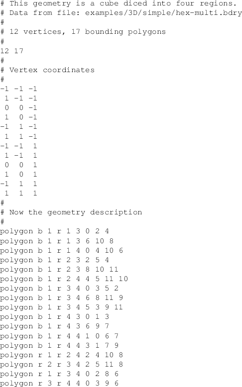
The first line of the file contains the number of vertices and number of boundary sections in the file. The next NVerts lines give vertex coordinates. The remainder of the file describes the boundary geometry. A sample input file and a picture of the underlying geometry are shown in Figure 3.6.
Each boundary data entry begins with a tag describing the kind of data it contains. At present, the only valid tag is polygon.
Next, the relationship between the boundary entity (BE) and the domain
is established. For entities lying on the bona fide domain boundary,
a boundary condition must be specified, along with an integer tag
(1 ![]() tag
tag ![]() 126) identifying which interior region is adjacent
to the BE. Entities lying within the domain necessarily separate two
regions with different ID tags; both tags must be specified.
126) identifying which interior region is adjacent
to the BE. Entities lying within the domain necessarily separate two
regions with different ID tags; both tags must be specified.
Finally, geometric data required to describe the BE must be given. This data is not restricted to a single line in the input file.
A polygon is specified by giving the number of vertices in the polygon, followed by the indices of the vertices, in order. These indices begin from 0.